 LiU Homepage
Engine laboratory
The engine laboratory is found in direct connection to the main vehicular corridor. The laboratory is equipped with two engine test stands, both having modern asynchronous machines capable of both driving and braking the combustion engines. The engines are controlled using dSPACE-equipment, with a fully transparent control system built in Matlab Simulink and executed in real-time. The main cell measurement system is built around an HP VXi mainframe, but also a real time Linux computer environment as well as built in measuring capability of the dSPACE control system hardware is used extensively.Engines
The two engines currently installed differs significantly, thus enabling a broad spectrum of research. Most of our measurements concern in-cylinder pressure, ion-current, charger/manifold pressure and temperature, engine speed and torque, lambda, turbo charger speed etc.LNF-engine
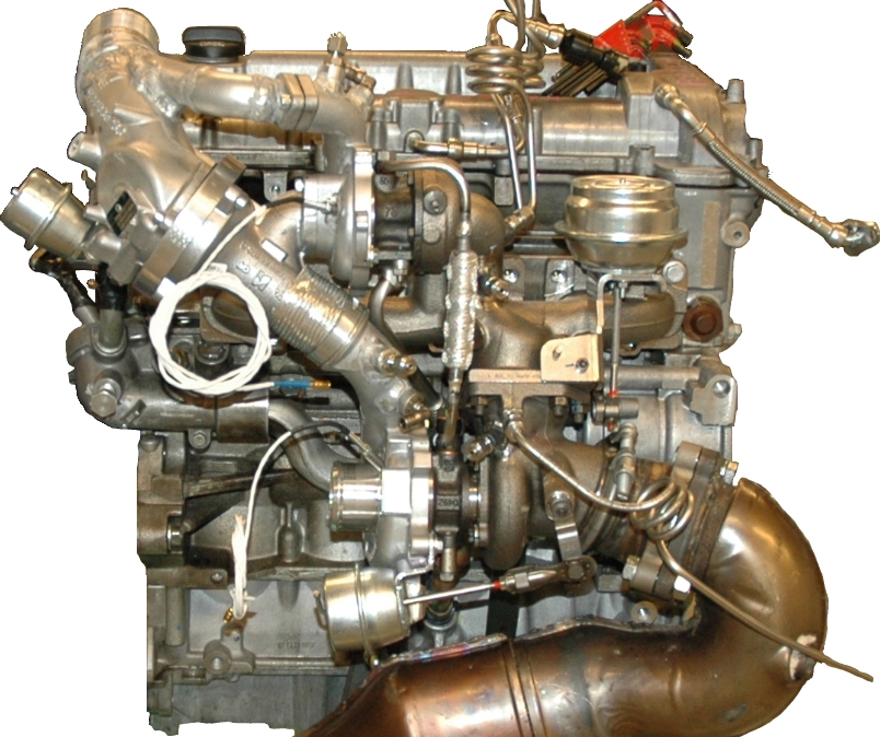 Test stand 1 is equipped with a 4 cylinder 2L gasoline engine with 16
valves. The engine uses direct injection, dual variable cam phasing,
and oil cooled pistons. The charging system is a two stage series
sequential turbo system. The low pressure stage is a BorgWarner
K04-2270 turbo (~190.000rpm maximum speed), and the high pressure
turbo is a BorgWarner KP35-1574 (~260.000rpm maximum
speed). Compression ratio is fixed to 9.2:1, and the engine is
"square" with bore equal to stroke (86mm). The base line engine was
installed in 2008, then having a single stage twin scroll turbo
system.
Test stand 1 is equipped with a 4 cylinder 2L gasoline engine with 16
valves. The engine uses direct injection, dual variable cam phasing,
and oil cooled pistons. The charging system is a two stage series
sequential turbo system. The low pressure stage is a BorgWarner
K04-2270 turbo (~190.000rpm maximum speed), and the high pressure
turbo is a BorgWarner KP35-1574 (~260.000rpm maximum
speed). Compression ratio is fixed to 9.2:1, and the engine is
"square" with bore equal to stroke (86mm). The base line engine was
installed in 2008, then having a single stage twin scroll turbo
system.
The base line engine was rated at 260hp and 350Nm, however the maximum
power has decreased after the installation of the two stage system in
2009. The two stage system originates from a SAAB 9-3 TTiD
application, and the low pressure stage compressor is smaller than the
original single stage compressor, thus causing the drop in maximum
power. The high pressure stage compressor by-pass has been exchanged
for an actively controlled valve.
 Though one can not speak of normal setup, since the engines are for
research, a summary of commonly measured signals is given
here. However, see it only as an indication, and every experiment
normally adds more sensors.
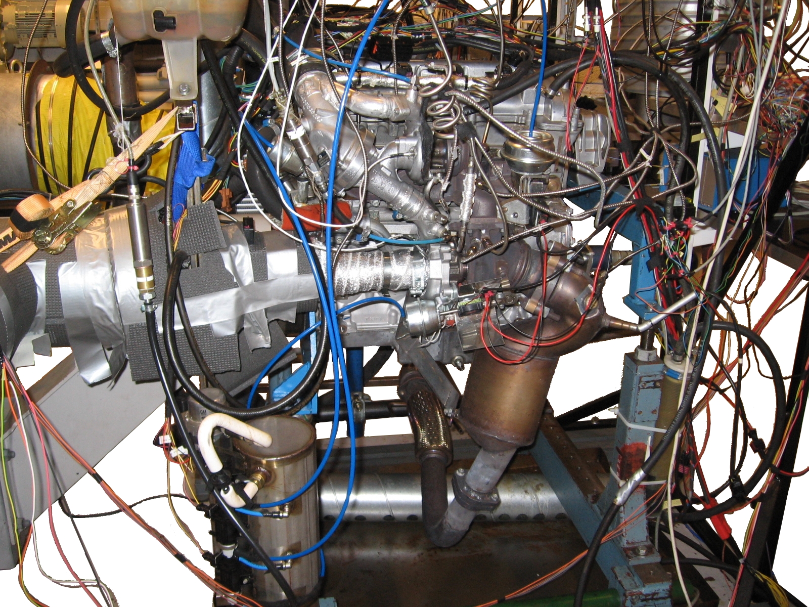
Apart from the cell sensor installation, also engine production
sensors are sampled: Mass flow, pressure before and after main
throttle, temperature before throttle, engine speed and position
(58X), cam phases, fuel rail pressure, vacuum tank pressure, main
throttle position (two sensors), air to fuel ratio (broad band
lambda), and system voltage level.
Though one can not speak of normal setup, since the engines are for
research, a summary of commonly measured signals is given
here. However, see it only as an indication, and every experiment
normally adds more sensors.
Apart from the cell sensor installation, also engine production
sensors are sampled: Mass flow, pressure before and after main
throttle, temperature before throttle, engine speed and position
(58X), cam phases, fuel rail pressure, vacuum tank pressure, main
throttle position (two sensors), air to fuel ratio (broad band
lambda), and system voltage level.
| Signal | |
| Pressure | Ambient, air filter, low/high pressure stage compressors, before/after intercooler, intake manifold, exhaust manifold, before/after high pressure stage turbine, low pressure turbine outlet, catalyst, in-cylinder pressures |
| Temperature | Ambient, air filter, low/high pressure stage compressors, before/after intercooler, intake manifold, exhaust manifold, before/after high pressure stage turbine, low pressure turbine, center of catalyst, engine coolant |
| Speed | Low and high pressure stage turbos, engine (speed and crank angle degree) |
| Mass flow | Air mass flow |
| Position | High/low pressure turbine waste gates, high pressure stage compressor bypass valve |
The actuators to control on the LNF engine are: main throttle PWM, high and low pressure wastegate PWM, high pressure compressor bypass PWM, ignition angle, dwell angle, intake and exhaust cam phasing, high pressure fuel pump PWM, injection timing, injection length, and number of injections.
SVC-engine
The (S)AAB (V)ariable (C)ompression engine sits in the second test
stand. The engine has variable compression ratio that can be altered
in real time .
 The compression ratio can be varied between roughly 8
and 14. The engine is a 5 cylinder 1.6L gasoline engine with a
mechanical compressor, driven by the engine crank shaft. The
compressor can be disconnected using a magnetic clutch, and by-passed
using a butterfly throttle valve. The engine was originally developed
to replace a 3L natural aspirated V6 engine, thus having performance
target of roughly 200hp and 300Nm.
The compression ratio can be varied between roughly 8
and 14. The engine is a 5 cylinder 1.6L gasoline engine with a
mechanical compressor, driven by the engine crank shaft. The
compressor can be disconnected using a magnetic clutch, and by-passed
using a butterfly throttle valve. The engine was originally developed
to replace a 3L natural aspirated V6 engine, thus having performance
target of roughly 200hp and 300Nm.
The SVC is a prototype engine, that has never been in production. The original concept was developed during the late 80s and early 90s. The engine was only hand built in a low number, and due to this Vehicular Systems have collected roughly 2.5 spare engines. The engine is said to withstand engine knock.
Control system
The main engine control system is a real time system utilizing equipment from dSPACE. The system consists of a MicroAutoBox that, mainly, runs the code and a RapidPro-system that is used mainly as an I/O-system. The code is compiled from a Simulink model, that is developed in-house. The control system is fully transparent to the user, enabling full control of all signals. The control system development is mainly conducted in the Simulink environment, from where the compilation of the code is also done. dSPACE ControlDesk is then used to download the code to the MABx.Test stands and test cell equipment
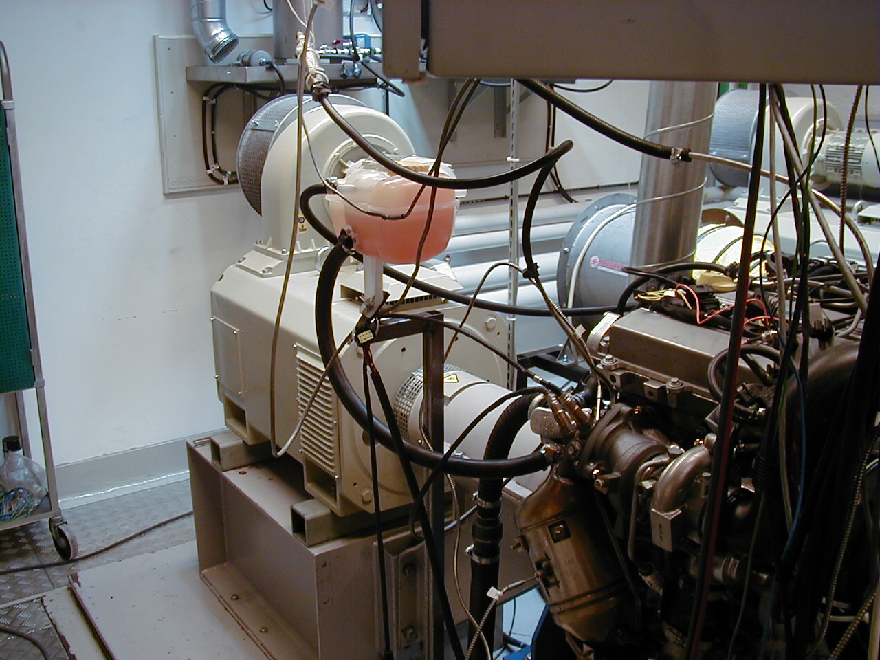
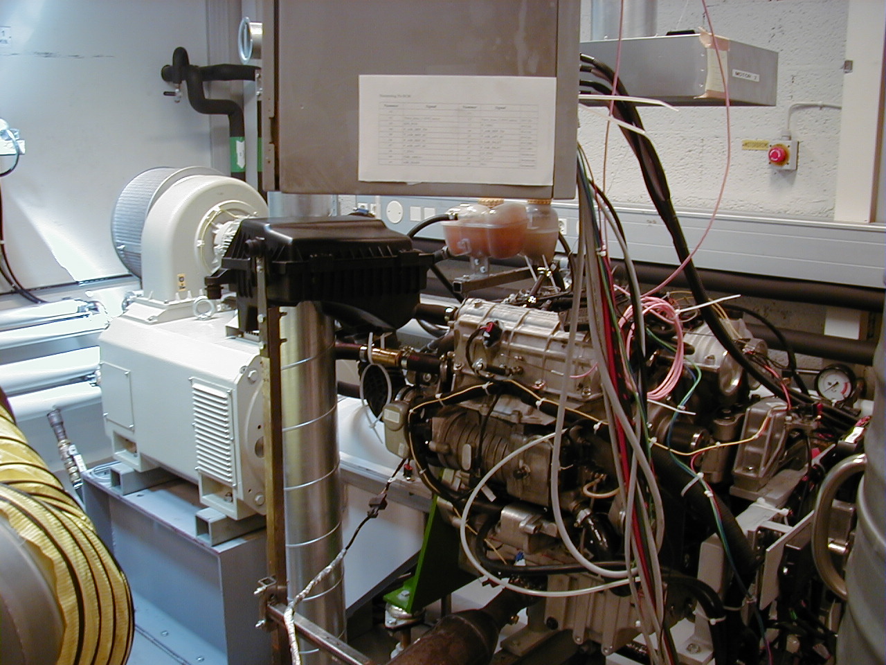
We have two engine test stands suited for testing
passenger car engines. Both test stands are equipped with modern
asynchronous machines which can act both as a drive and a load to the
engines.
 These test stands gives us the possibility to run both steady state
and dynamic tests, with torque rise-times less than 10 ms. The
dynamometers can be used to simulate vehicle behavior, and run test
cycles (e.g. NEDC, FTP75). By connecting the measurement system to the
dynamometer and letting the measurement system control the behavior of
the dynamometer we do automatic engine mapping and cycle tests.
The sensory equipment of the dynamometers include a shaft speed
sensor, as well as applied torque. The test cell is restricted to only
operate one engine at a time.
These test stands gives us the possibility to run both steady state
and dynamic tests, with torque rise-times less than 10 ms. The
dynamometers can be used to simulate vehicle behavior, and run test
cycles (e.g. NEDC, FTP75). By connecting the measurement system to the
dynamometer and letting the measurement system control the behavior of
the dynamometer we do automatic engine mapping and cycle tests.
The sensory equipment of the dynamometers include a shaft speed
sensor, as well as applied torque. The test cell is restricted to only
operate one engine at a time.
The electricity produced by the dynamometer, when loading the engines, is fed back to the B-building, through a dedicated transformer station located in the engine lab building. The coolant water also recirculates, and contributes to the heating of the B-building. The fuel supply to the engines is found in a dedicated, highly ventilated, room. Fuel is pumped, using compressed air pumps, from the fuel storage room into 12L tanks inside the engine test stand room. Production fuel pumps then feed the fuel rails of the engines.
Both dynamometers were replaced after a small fire in year 2001. The new dynamometers are asynchronous machines delivered from Schenck and have a braking capability of 250 kW (~340 hp) and a rated torque of 480 Nm. The dynamometers also act as start motors for the combustion engines.
| Test stand 1 and 2 | |
| Type | Schenck Dynas3 LI 250 |
| Power [kW] | 250 |
| Maximum Speed [rpm] | 10 000 |
| Rated Torque [Nm] | 480 |
Measurement equipment
Three measurement systems are currently used in the engine test
laboratory; an HP VXI system, a dSPACE RapidPro/MicroAutoBox
system, and a real-time capable Linux computer with an NI I/O-card.
The VXI mainframe is fitted with a fast 8 channel digitizer + DSP
capable of anti-alias protected sampling up to 196 kHz/ch and a slower
module more suited for stationary measurement of up to 64 channels of
combined voltage, temperature, current and frequency input/outputs.
The slower module is also capable of closed loop control. All VXI
components are delivered by Hewlett-Packard.
The dSPACE equipment is mainly used as the real time control system of
the engines, but is also capable of measuring both analogue and
digital signals with sampling frequencies up to CAD-based.
The real-time Linux computer is also capable of control, but is
currently mainly used as to graphically present and analyze
in-cylinder pressures.
| # | Model & Description |
| 1 | HPE8400A & 13-slot, C-size VXI mainframe, (199808-\#US37000606) |
| 1 | HPE8491A & Measurement system controller with serial Firewire bus. (199808-\#US37000220) |
| 1 | HP VXI, HPE1415 & 64-channel algorithmic closed loop controller. 16-bit A/D-resolution, up to 56kSa/s maximum reading rate dependent upon configuration. 64kSa measurement FIFO memory built in. (199808-\#US35000422) |
| 3 | HPE1503A& 8-channel programmable filter and gain Signal Conditioning Plugon (SCP); provides eight programmable, 2-pole low-pass filters with cutoff frequency setting of 2, 10 and 100Hz, as well as a 1.5kHz ``pass-through'' mode (filter OFF), and further selectable amplifier gains. (199808,199902,200002) |
| 1 | HPE1505A& 8-channel current source SCP (199808) |
| 1 | HPE1537A& 4-channel voltage output SCP (199808) |
| 1 | HPE1538A& 8-channel enhanced frequence/totalize/PWM SCP; each of the eight channels can be individually configured to perform input or output functions. Input function include frequency measurement and totalize, pulse width measurement, rpm, and quadrature count.(199808) |
| 1 | HP VXI, HPE1433 & 8-channel 196 kSa/s digitizer (+DSP) with integrated transducer signal conditioning, anti-aliasing protection, digitization and high-speed measurement computation. 32Mb of RAM. Separate A/D converter ($\Delta/\sum$) for each channel. (Options selected: AFV - voltage input breakout box E3240A with AXM--Dual rack mount kit, ANC - 32MB total RAM, AYF - add tachometer input, 199808-\#US38040602) |
| 1 | RP/MABx & dSPACE Microautobox and RapidPro-system. |
| 1 | Real time Linux computer with I/O capabilities |
Commonly used sensors
Though no "normal" sensory equipment can be given, this section still summarizes some of the "normal" sensory found on the LNF engine.Pressure sensors
| # | Model & Description |
| 3 | Kistler 4260A50 BXLB00G1 & Absolute 3.4 Bar, 0-5V, MIL-C-26482 connector, M10x1 pressure port [0.05\% FS accuracy, 0.1\% FS stability per year, 3xFS proof pressure, $f_{max} = 2\textrm{ kHz}$] (2009-\#2073203,2073204,2083205) |
| 1 | Kistler 4260A75 BXLB00G1 & Absolute 5 Bar, 0-5V, MIL-C-26482 connector, M10x1 pressure port [0.05\% FS accuracy, 0.1\% FS stability per year, 3xFS proof pressure, $f_{max} = 2\textrm{ kHz}$] (2009-\#2073190) |
| 1 | Kistler 4260AB03 BXLBD0G1 & Bi-directional differential, 0.17 Bar, 0-5V, M10x1 pressure port, reference port 1/4 AN 7/16-20 UNF Male Class 2A male to SAE J514, MIL-C-26482 [0.2(0.05)\% FS accuracy, 0.1\% FS stability per year, 3xFS proof pressure, $f_{max} = 2\textrm{ kHz}$] (2009-\#2073190)\\ 3 & Kistler 4295A2 & Absolute 2 Bar, 0-10V (199911x3-\#845073,845074,845075) |
| 3 | Kistler 4295A2V & Absolute 2 Bar, 0-5V (199903-\#852230,199903-\#852231, ???-\#925837) |
| 1 | MicroSwith Honeywell 164PC0137 & LFE3 differential pressure sensor 0-10 inch H20), 0.5V/inch H20, 0-5V (email from Elbert Hendricks) |
| 2 | AVL GU21D & Cylinder pressure, (newly calibrated sensors installed on the LNF 2008, by GM/SAAB, \#4285,4286) |
Temperature sensors
| # | Model & Description |
| 2 | Pentronic & 1.5mm, 2m length, Thermocouple Type K, class 1 according to IEC 60584, (2008-\#085211078, 08511079) |
| 10 | Pentronic & 3.0mm, Thermocouple, mounted on LNF |
| 6 | Pentronic & 3.0mm, Thermocouple, in locker |
| 5 | Pentronic & 3.0mm, Thermocouple, in lab |
| 3 | DTU & Elbert Hendricks temperature sensors |
Misc sensors
| # | Model & Description |
| 2 | Gill Blade 25 position sensor, 0-25mm, $f_{max}=1\textrm{ kHz}$, max $125^oC$ |
| 2 | Acam PicoTurn, turbo speed sensor, PTBM V6, 200-400000rpm (0810-??, 10-\#1210.091104.0020, sensors lp=\#0586.070615.037, hp=\#0586.080428.001) |
| 2 | GIF torque sensor on the Schenk dynamometer. For the LNF engine: ``P/N: 2155 / 12.12.01'', ``S/N: Stator - F1 -1145'', rated torque = $650 \textrm{Nm}$, sensitivity: $29,229 \textrm{Hz/Nm}$, ``CAL.SIGNAL = $101.9 \textrm{Nm}$'', ``MAX SPEED = $12000 \textrm{RPM}$''. Studying the GIF homepage reveals that our model is most likely ``F1''. Emailed GIF 2012-01-11: asking for a manual and sensor characteristics. Received calibrations sheets for our sensors, as well as a manual for the evaluations unit from Jan Stoffel, GIF 2012-01-12. |
| 1 | B235R MAF orginal BOSCH |
| 2 | LeineLinde & 720ppm, crank angle sensor, $N_{engine}$-sensor |
| 1 | Bosch continuous $\lambda$-sensor with ETAs equipment |
Informationsansvarig: Oskar Leufven
Senast uppdaterad: 2013-09-02
